Stainless Steel Unequal Angle Capacity Check
Design according to SCI P291
Section Dimensions (mm)
La = mm Length of leg a
Lb = mm Length of leg b
t = mm Thickness
Figure 1: Geometry
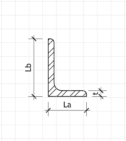
L-Section Dimensions
Material Properties (MPa)
fy = MPa Yield strength
fu = MPa Ultimate tensile strength
G = MPa Shear modulus
E = MPa Elastic modulus
Material Factors
γm0 = Material factor for cross-section resistance
γm1 = Material factor for buckling resistance
Applied Loads
Ned = kN Axial force (compression is positive)
Med,x = kNm Moment about major axis
Med,y = kNm Moment about minor axis
Ved,x = kN Shear force parallel to leg b
Ved,y = kN Shear force parallel to leg a
Lbuckling = mm Buckling length
Ag = (La + Lb − t) · t = 1900 mm² Gross area
Av,x = Lb · t = 1000 mm² Shear area for Ved,x
Av,y = La · t = 1000 mm² Shear area for Ved,y
Zpl,x = 10000 mm³ Plastic modulus (major axis)
Zpl,y = 10000 mm³ Plastic modulus (minor axis)
Axial Compression Check
Nc,Rd = fy · Ag / γm0 = 362.73 kN
Axial utilization: Utilaxial = 0.634
Shear Check
τy = fy / √3 = 121.24 MPa
Vpl,Rd,x = Av,x · τy / γm0 = 110.22 kN
Vpl,Rd,y = Av,y · τy / γm0 = 110.22 kN
Shear utilization (x): Utilshear,x = 0.000
Shear utilization (y): Utilshear,y = 0.000
Max shear utilization: Utilshear,max = 0.000
Bending Check
Mc,Rd,x = Zpl,x · fy / γm0 = 1.91 kNm
Mc,Rd,y = Zpl,y · fy / γm0 = 1.91 kNm
Bending utilization (x): Utilbend,x = 0.000
Bending utilization (y): Utilbend,y = 0.000
Combined bending utilization: Utilbend,combined = 0.000
Combined Forces Check (Simplified)
Combined utilization (axial + bending): Utilcombined = 0.634